EEC IV Inner Workings
By tmoss
Last Revised: 12/17/2002
There are a lot of questions regarding the way the Mustang EEC IV works. I have spent significant amount of time searching for information regarding the EEC and I have come across readily available reliable sources of information. I don’t know that I can improve on the explanation of this information by pulling it into one document, but I am willing to try for the benefit of fellow Stangers. Many thanks to Authors such as Tom Cloud, Mike Wesley who have technical articles on the net, Charles Probst, who authored the "Official Ford Mustang 5.0 Technical Reference & Performance Handbook from which information was derived, and Mustang Forum members such as Rick Wagner, who used a EEC-Tunerâ and TransmarrowBird Eater (Dave) for sending me his TwEECerâ logs for graphing.
Objectives
The EEC objectives include calculating required command values and outputting the required voltages to command, in real time, the spark timing, the EGR valve position, and for controlling the on/off duty cycle of the fuel injectors.
Diagnostics
Two types of diagnostics are present in the EEC, On-Demand and Continuous. On-Demand is conducted during key-on/engine-off and during engine running modes to allow the EEC to test itself. Continuous is on anytime the EEC is in operation. Conditions found during Continuous operation are stored in special memory called "Keep Alive Memory" (KAM), which is 128kb of read/write memory. KAM receives its power directly from the battery. If the car battery is disconnected, or if the battery voltage falls too low, the KAM is preserved capacitors internal to the EEC. Stored codes are very useful in determining potential trouble. They are widely published on many web sites and so, will not be listed here.
Fuel Control
Determining how much fuel to deliver is accomplished in two ways, Speed Density (SD) control or Mass Air Flow (MAF) control. The mass airflow sensor measures the *MASS* of the air going into the engine. By measuring the *MASS* of the air, this helps to compensates for air density changes that occur with altitude and weather changes. The air temperature sensor, the engine temperature sensor, and the Oxygen Sensors (O2 or HEGO) are also used to help determine fuel and timing requirements. Both the MAF and SD systems use barometric compensation with the exception of the ‘94-’95 Mustangs which incorporate that function into the MAF. The SD system uses a Manifold Absolute Pressure sensor (MAP), which measures the absolute pressure (vacuum) in the intake manifold. When the ignition is first turned on, the EEC takes a quick reading of the MAP and stores that value as atmospheric barometric pressure for calculations during running. In the MAF cars, the Barometric Absolute Pressure sensor measures barometric pressure directly and continuously.
The EEC does not control injector "on" time from just a *single table *. The EEC calculates this time by monitoring sensors, and calculating "on" time based upon fuel flow for a 19lb fuel injector at 39 psi for a targeted air/fuel ratio that is stored in a multi-dimensional table for engine conditions as monitored from the engine sensors.
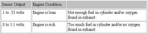
There are two methods of EEC fuel control, Open Loop and Closed Loop. The EEC starts in Open Loop and based upon time and engine parameters such as engine temperature, changes to Closed Loop. During Open loop operation, the O2 sensors are not used to trim air/fuel mixture and hence the name "open" loop. Closed Loop operation consists of an EEC controller that uses a target air/fuel ration contained in lookup tables (based on a Ford test engine) that uses the O2 sensors as feedback for making adjustments. If the output of the O2 (HEGO) sensors stay either below .33 volts or above .8 volts, then the engine is running too lean or too rich. Here is a graph of the two output levels that signify out-of-tolerance values that cause correction factors to be calculated by the EEC and applied to the injector pulse width as well as being written to correction tables in KAM, which is called Adaptive Control. The Tweecer logs these as 3.2v & 4.9v values.
The EEC varies A/F ratios by varying the "pulse width" of the voltage applied to the injector solenoid. Pulse width is a term to describe how much average voltage is applied to an injector coil over a given time span - typically about 2.5 milliseconds for EFI cars. 12vdc is always applied to the injectors but when you average the applied voltage over a set time span, shorter pulses result in lower average voltage (leaner A/Fs) over that time period and vise-versa (richer A/Fs) for a given air flow quantity
Anything external to the EEC, which tries to modify the desired air/fuel ratio (based upon data from a Ford test engine – hence the name "base" Open Loop Fuel Table) in closed loop operation, will cause the computer’s Adaptive Control feature to try to compensate for the change by writing correction multipliers to KAM that correspond to the load level at which the out-of-tolerance value occurred. The Adaptive Control will also monitor how the engine is responding to the way you drive and make adjustments. Your ET may improve slightly after several runs as the Adaptive Strategy shifts from street driving to drag racing. According to Mike Wesley, this control feature can only make adjustments in a range of 25% of desired values. EEC-Tuner user Rick Wagner has data logged his car and found that adaptive control only varies ±12.5% or 25% overall. Below are graphic representations of the Open Loop and Wide Open Throttle air/fuel ratio "base" table for an A9L Mustang computer and a 95 Mustang computer.
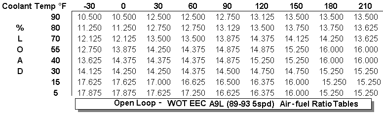
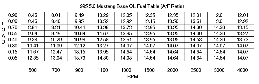
Notice that there are variances between the table values for different year cars. These tables also vary for differences in transmissions, etc. % load in the graph table is calculated by the MAF based on airflow and other sensor inputs. In the case of SD (not illustrated here), the load is based on Ford’s volumetric efficiency (VE) values for the 302, which are contained in the EEC tables.
EEC Controls
Functions controlled by the EEC are: air/fuel ratio in closed loop, EGR position, (gasoline) canister purge, thermactor system, adaptive control system, fuel injectors, transient fuel, spark, VE tables, rev limits, and much more.
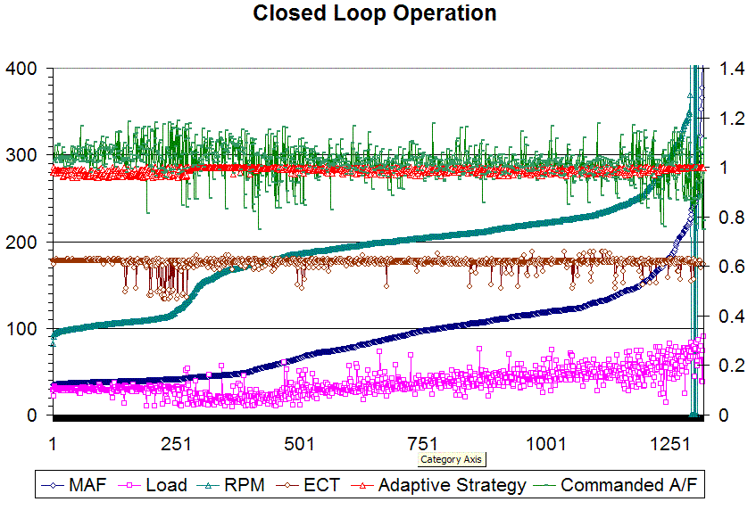
Closed loop operation can sometimes be modified without problems and within EPA guidelines. This has allowed some manufacturers to market cars and parts that are emissions legal (e.g. Kenne Bell – for which Mike Wesley has done work, and Saleen). Approximately 900 items in a 93 Mustang can be changed or logged. For example, during a shift, the EEC might look at spark, load, TPS, fuel, and transient fuel. By logging this data, you can tell just where in the table the EEC is looking and tune those cells only rather than tuning the whole curve or somewhere where the EEC isn’t even looking at table values. Below is a graph of data collected by Rick Wagner, which illustrates the conditions under which his EEC made the transition to closed loop. One thing that stands out here is that temperature is only one of the parameters that the EEC looks at for closed loop. This A3M computer (same base tables as A9L) went into closed loop with ECT temps down to 140 degrees.
The EEC sees only one crank position sensor signal, a short signal on the shutter wheel in the distributor shutter wheel. The Hall effect "pickup coil" as it is generally known has a magnetic field that is interrupted from the sensor by a wheel containing shutters that spin past the sensor. The signal output from the Hall effect sensor is called a Profile Ignition Pickup (PIP) signal. There is one shutter that is skinny and this is how the EEC knows the #1 piston top dead center position by its mechanical relationship through the timing chain and distributor gear. This is also how the EEC knows where each cylinder is in the firing order due to monitoring the time rate between PIP signals (changing rpms) and the internal firing order data, which enables it to control sequentially the firing of the injectors. Below is a figure of a good PIP signal, which is routed through the Thick Film Ignition (TFI) to the EEC for processing and timing control, which the EEC then sends the signal to the TFI module to actually fire the coil. The EEC senses the coil ground for feedback that the coil has actually fired as commanded by the TFI.
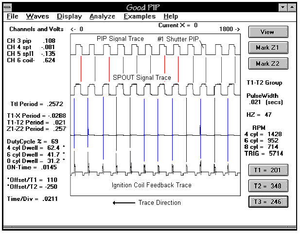
The TFI module cleans up the PIP signal before sending it off to the EEC. The TFI also uses the Spark Output (SPOUT) signal, from the EEC, to determine when to fire each plug. The coil fires on the falling edge of the SPOUT signal. The TFI also provides an internal SPOUT signal (based on the PIP signal) for limp home mode operation if it senses the EEC has stopped sending the SPOUT. If the SPOUT plug is not inserted, spark timing remains at base timing during engine operation.
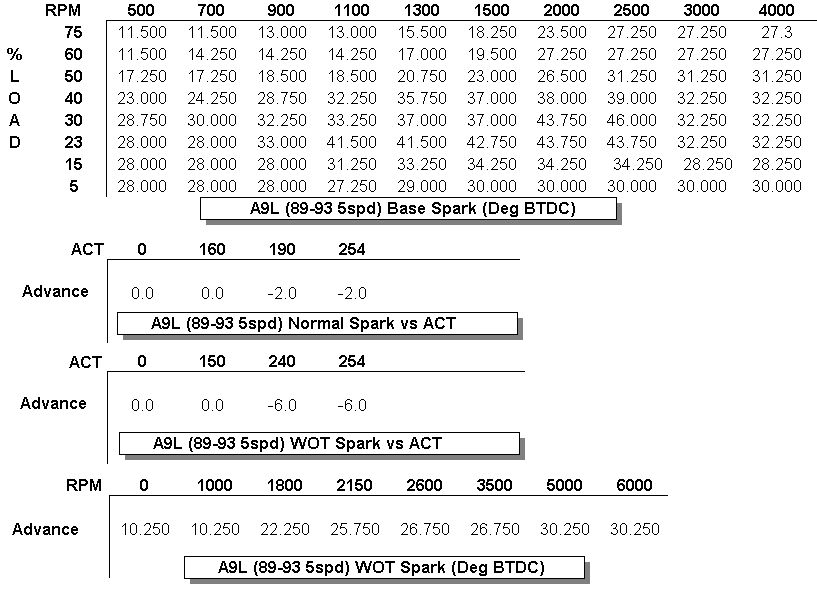
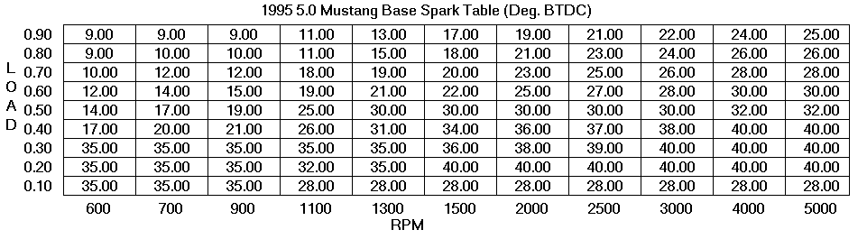
The EEC controls the spark based upon lookup tables like the air/fuel mixture. Below are figures of the A9L spark table with conditions under which it is modified and a ‘95 spark table. The computer interpolates (ratios) values for load and rpm between the table values so timing is adjusted for every cylinder firing. Once again the MAF signal and other sensors measure % load and a value of spark is chosen based upon engine rpm. Notice that at 190°F the EEC pulls 2 degrees of timing. Also notice that at Wide Open Throttle (WOT) that spark is determined by engine temperature and rpm only. The spark curve is not really aggressive when compared to distributor curves of pre-computer controlled cars. This is one table value that can be changed for better performance. Performance mechanical advance distributors have full advance by about 2,500 rpm. Notice in this table that the EEC timing doesn’t all come in until 5,000 rpm at WOT. Note: This table may DIFFER for different model/year of EEC controllers.
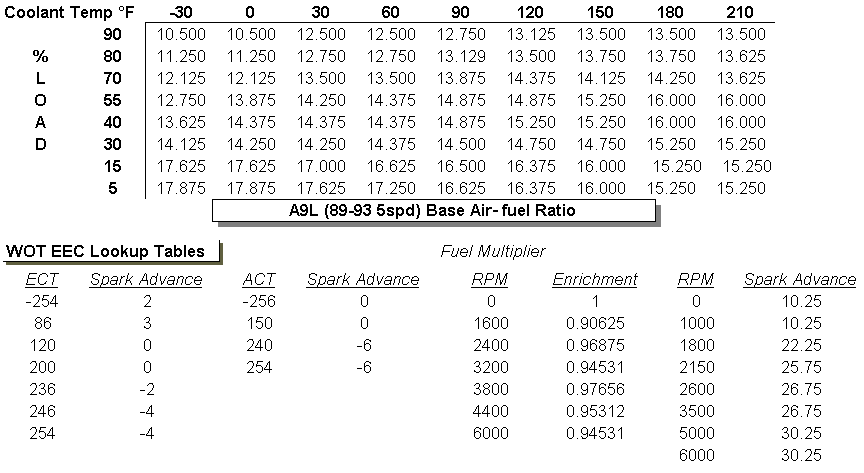
The WOT Air/Fuel table is used during wide-open throttle only. Below is the Open Loop/WOT fuel/air table and it’s modifiers for WOT. Notice fuel enrichment is increased through 3,800 rpm where it is reduced with increasing rpm.
Adaptive Control
There is much confusion about how Adaptive Control works especially at WOT. Adaptive control, according to Mike Wesley and Charles Probst, is always functional – at WOT and anything less than WOT. The difference is that in open loop and at less than WOT, this feature monitors O2 sensors and writes correction trim factors to KAM, which are applied to the base table value for future calculations. This is accomplished by varying injector pulse width. The rate at which Adaptive Control writes these correction factors to KAM is slow enough to filter out short duration upsets in the mixture. Short-term closed loop corrections are written to Long-Term Adaptive Strategy KAM if they are repeatedly seen out-of-spec by the O2 sensors . At WOT the Adaptive Control still functions but it does not update (or write) correction factors to KAM for application to the base tables – it defaults to the already stored trim values, if any have been written, for the load and engine temperature experienced in the WOT load range.
So, we can deduce that if you increase or decrease fuel pressure and no target base table A/F ratio values are exceeded (high or low) then no correction trim values will be written to Keep Alive Memory (KAM) to be used as multipliers for the base air/fuel table
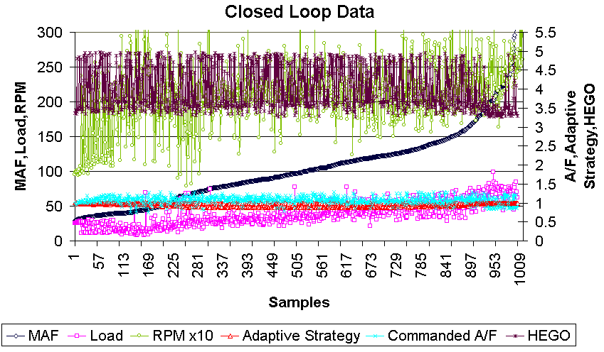
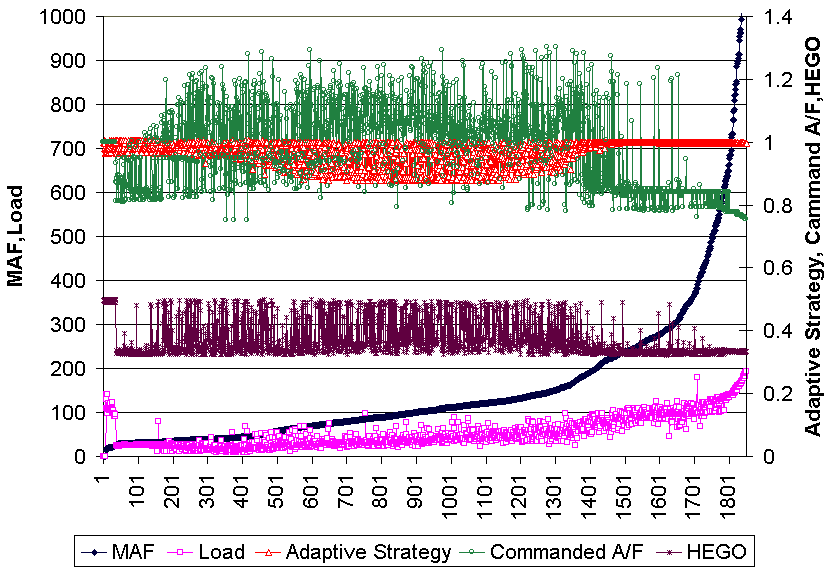
. Also remember, the corrections are limited to about 25%, so if you change fuel pressures beyond the ability of the EEC to correct, it will not be able to tune out your fuel pressure changes. I have read posts by many people saying that they varied their fuel pressure and didn’t think that the adaptive control function took their change out. Below is a graph of Rick Wagner’s Tweecer log which shows that when the HEGO sensed a rich condition (3.2v occurring at about sample #897) the EEC adjusted Adaptive strategy to try and compensate – this shift is a little harder to see as I had to scale the right hand Y axis to include the larger HEGO signal but the shift is clear if you look closely. In the graphs below, the EEC is adding fuel if the Adaptive Strategy is above 1.0.Closed Loop
When the EEC reaches a point where it is satisfied with all monitored parameters, it will transition to closed loop operation. In this mode the EEC tries to control air/fuel mixture to the stoichiometric ratio of 14.7:1 and accomplishes this by adjusting injector pulse width with feedback from the O2 sensors to control to the 14.7:1 ratio. This will occur when the EEC table values are calling for the ratios close to stoichiometric 14.7:1 air/fuel ratio. In warm up mode or WOT the O2 sensors are not used because they can only send signals that indicate a ratio above or below 14.7:1 and cannot read a ratio directly. You’ll see in the table that ratios in these operating areas are outside the 14.7:1 range. In graphing the parameters of thousands of data samples during closed loop operation, we have seen the EEC go into closed loop at a temperature less than 170°F since Rick Wagner sent more data from the last revision. When temperature gets to 190°F, the A9L EEC pulls 2° of timing, so a 180°F thermostat is probably the best performance choice. Here are a couple of Tweecer data graphs.
A word of caution to those who install long tube headers. In order for the O2 sensors to operate properly, they must be at, and stay at, a minimum temperature. If you place the HEGO O2 sensors farther away from the head than the stock location, you may have the sensor too far away to keep it hot enough to read correctly due to the cooled exhaust gases. This causes the EEC to enrich mixture and may cause plug fowling. Ceramic heat coating the headers will help maintain exhaust gas temperature. The EEC has a timing table used to time the sampling of the O2 sensors to coincide with the arrival of the latest cylinder exhaust pulse from each bank. Moving the HEGO sensor further away (or closer for that matter) may result in an ill-timed sample, which could also cause improper air/fuel mixtures to occur due to the O2 sensor not sampling when the pulse passes the sensor. One way to compensate for the additional time needed due to adding length in the Long tube headers is to change the timing table with an EEC-Tunerâ or TwEECerâ .
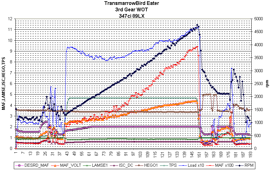
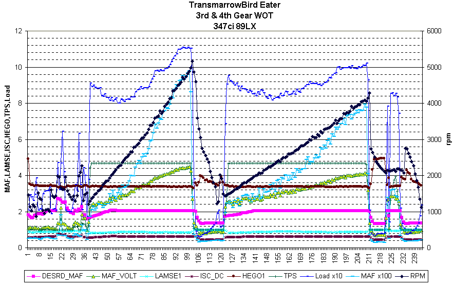
The next two graphs were from data contributed by Dave (sorry didn’t give last name) who goes by TransmarrowBird Eater on the forums. These depict two runs, one in third gear where he slows down and then speeds up and the second is of a 3rd-4th gear run. LAMSE1 is that A/F correction trim factor mentioned previously to get the target air/fuel mix and you can see it react in these graphs as well.
There are significant differences in the design and function of the 94-95 EEC as compared to the older EECs. In 1994 Ford did a redesign of both the EEC hardware and EEC software. The end result was a much cleaner, smoother running car. You may have heard of problems getting them to start, idle, and run like a 1987 - 1993 5.0 after doing some modifications. The following information was taken directly from Mike Wesley’s article "EEC vs. EEC".
"In the 1993 and older EECs, spark advance at WOT (Wide Open Throttle) was based purely on RPM. When you went WOT, the EEC jumped to a separate spark function to give what Ford thought was the best spark curve. In the 94-95 cars, Ford made a major change to the spark calculations.
The WOT spark function was deleted and now the car uses the same spark tables for both part throttle and WOT spark calculations. The problem with this is the spark table is based on RPM and Load. The formula for Load is basically the amount of incoming air, ratioed against how much one cylinder can hold at standard pressure/density. You can think of Load as volumetric efficiency. The EEC uses the MAF to determine Load. It is a direct measurement of how much air is entering the engine. You might be wondering what the big deal about Load is. Well, since Load is used in the spark calculations, any change in Load will affect how much advance you get. Since the EEC uses the MAF to determine Load, any change in the MAF will change the Load calculation. Changes in the cam and anything that puts more air into the cylinders will also affect Load. Change the flow characteristics and you change Load.
When you go into WOT, the EEC will pull spark values from the top two rows of the table. In a bone stock 94 GT as RPM increases, Load decreases and spark advances a bit. The decrease in Load is due to volumetric efficiency of the engine dropping off. A typical 5.0 is not the most efficient engine around. If you compare the spark values calculated by the 95 EEC to the 93 values, you'll see they are not too much different. Change something on the engine and it's a whole new ballgame. Let's take a MAF change as an example.
An aftermarket MAF's curve doesn't always follow the stock curve. When the EEC looks at the aftermarket MAF and converts the voltage into airflow using a built-in lookup function, it will calculate differing amounts of Load as RPM increases. In our example, we'll use 5500 RPM and 4.6 volts out of the MAF. In our baseline car at 5500 RPM, the EEC calculated a Load of .78. Input that into the spark table and we get advance a bit over 26 degrees. At 4.6 volts the aftermarket MAF 'fools' the EEC into thinking MORE air is entering the engine than what really is so it calculates a higher Load. With this particular MAF on our baseline car, we saw a Load value of .91 and the resultant spark advance was 25 degrees. Wow! By changing the MAF, we lost about 1.4 degrees of spark advance!
On the dyno, this particular car lost about 14HP when the aftermarket MAF was installed. Some of this was due to the loss in spark and fuel. It looks like there is a simple fix to this by bumping the distributor up. Sounds good, and it will help get back the loss in top end spark. However, there could be a catch if we now look what happened to this car at 2500 RPM. The baseline car had a Load value of .75 @ 2500 RPM and spark was 24 degrees. After putting on the MAF @ 2500 RPM, the Load was .65, and spark was roughly 26 degrees. Hmm. We got more bottom end spark with the MAF since it 'fooled' the EEC into thinking LESS air was entering the engine. Looks good so far and the car did make more power at 2500 RPM than it did stock. Now to fix the top end spark loss, we bumped the distributor up 5.5 degrees. This included the "normal" 4 degrees everyone puts into the car plus the extra spark to compensate for what we lost with the MAF. Now the car made up the lost power plus some on the top end and lost 10 HP at 2500 RPM. Why?
Due to what the MAF was telling the EEC, and how it changed Load and advanced the spark 2 degrees, our bump in the base advance made the total spark advance at 2500 RPM a bit over 30 degrees. Way too much advance at 2500 RPM. The very top point in a torque curve is called MBT or Maximum Brake Torque spark. It's basically the amount of spark advance that produces the maximum amount of torque. If you go above or below the MBT point, you lose torque. As you continue to advance the spark, you'll reach a point in the curve called BDL spark or Borderline spark. This is the amount of spark advance where the engine just begins to knock. On a normally aspirated, low compression engine, BDL occurs at advance values higher than MBT. On high compression or supercharged engines, BDL can occur at advance values lower than MBT. Raising the octane value of the fuel moves the BDL point higher up. Going back to our low RPM example, further testing found the MBT point at 2500 RPM to be 28 degrees. Now came the question of what to do. Should we lower the base advance to get the bottom end power back and sacrifice some top end power, or leave it alone? However, should we go for the top end power, but sacrifice the bottom end? That choice is up to the owner. We opted to actually re-calibrate the EEC to run MBT spark at all RPM points by changing the spark tables. Now of course all this might go the other way depending on the MAF. It can "fool" the EEC into lowering the Load at higher RPM, which will give you more advance. It's really hard to tell what you are going to end up with.
Another thing the '94 - '95 cars do with spark is retarding it during a shift. The automatic cars REALLY pull out the timing, but the 5spd cars do it also. Inside the 5spd EEC calibration is a thing called Tip-in Retard. Any time the throttle is moved from a more closed position to a more open position, it can pull out some timing. When you shift a 5spd car, most people lift off the gas during the shift. The EEC senses this, and when you push on the gas again it pulls some timing out. The older EEC didn't have this 'feature'. You lose more torque during a shift on a 94-95 car than a 93 or older car. Why did Ford do this?? We think warranty. Ford had to replace a zillion T-5's in the older cars. A lot of them broke due to overshifting and power shifting, but a lot of them broke as a result of too much transient torque. If you could reduce the torque output of the engine during a shift, the transient torque would be lower. The trans wouldn't break as easily, and thus the Tip-in Retard was born. How much timing is pulled out during a shift varies, but it can pull out as much as 15 degrees. There is not much you can do to 'fix' this except by re-calibrating the EEC.
The 94-95 automatic cars have a torque modulation strategy installed in them to vary spark during shifts. When the EEC thinks it's time to change gears, it can pull out massive amounts of timing so the shift is nice and smooth. As far as we know there are two reasons for this. First is warranty. The AODE trans is not all that strong in stock form. By reducing the torque during shifts, you can extend its life. Second is shift feel. For some reason Ford doesn't want you to 'feel' the car shift. Ever notice that just about all Ford vehicles with electronic transmissions shift like Town cars, smooth and sloppy. Even performance vehicles like Mustangs and Lightnings have weak kneed shifting. What fun is that? The downside to this smooth, sloppy shifting is increased wear. Ford tends to slip the trans too much during gear changes slowly burning it up. Manually shift your car, and you'll see it shifts much better. During manual shifts you run through different sections of the trans control strategy. The older EECs with AODs (sometimes called DOA's) really had no idea a trans was attached to the engine. They did not spark retard during shifts and could actually shift quite well. They broke more often, but shifting was better. Adding a shift kit to a 94-95 car can help the shift feel by increasing fluid pressures inside the trans, but this does nothing to the engine torque loss during a shift.
So you can probably see, tuning a 94-95 Mustang can be tricky. The engine remained basically the same, but the brains controlling it changed."